Abstract
This circuit appnote describes which factors need to be considered when selecting ceramic capacitors for modern low dropout regulators, highlighting the importance of capacitor oversizing for long-term reliability over the lifetime of the product.
Introduction
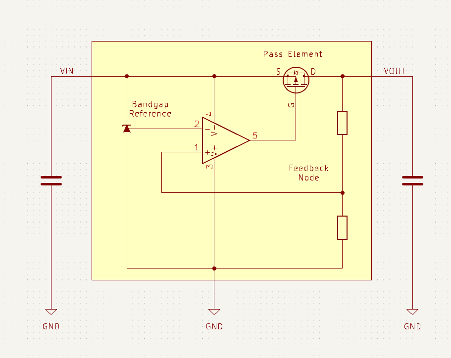
Linear Voltage Regulators control the desired output voltage by “burning off” the excess voltage between input and output using a pass Element which is either a type of BJT transistor or MOSFET and turn it into heat. An internal regulation compares the output voltage to the bandgap reference and adjusts the pass element accordingly. The output capacitor slows down the response of the control circuit and acts as an energy buffer to help with fast changes in the load current. The Input capacitor is less critical but helps with fast changes in the output (transients) and noise reduction (PSRR).
Although the basic working principle is simple, it is important to design your circuit in such a way that the regulation is stable; otherwise the output may oscillate.
Datasheet Parameters
Reputable semiconductor companies like ST Microelectronics, Texas Instruments, Analog Devices and Infineon provide detailed documentation for their products. Documentation from lesser known vendors is often incomplete, making component selection more difficult.
Apart from the main specifications like max. VIN, max. current, and package we will have to take a look at the required minimum and maximum values for capacitance and ESR (equivalent series resistance).
This graph was taken from the LDLN050 datasheet, it indicates that the output capacitor must have a ESR value of 0.03 Ω to 1 Ω the capacitance needs to be between 1 μF and 100 μF to guarantee stable operation.
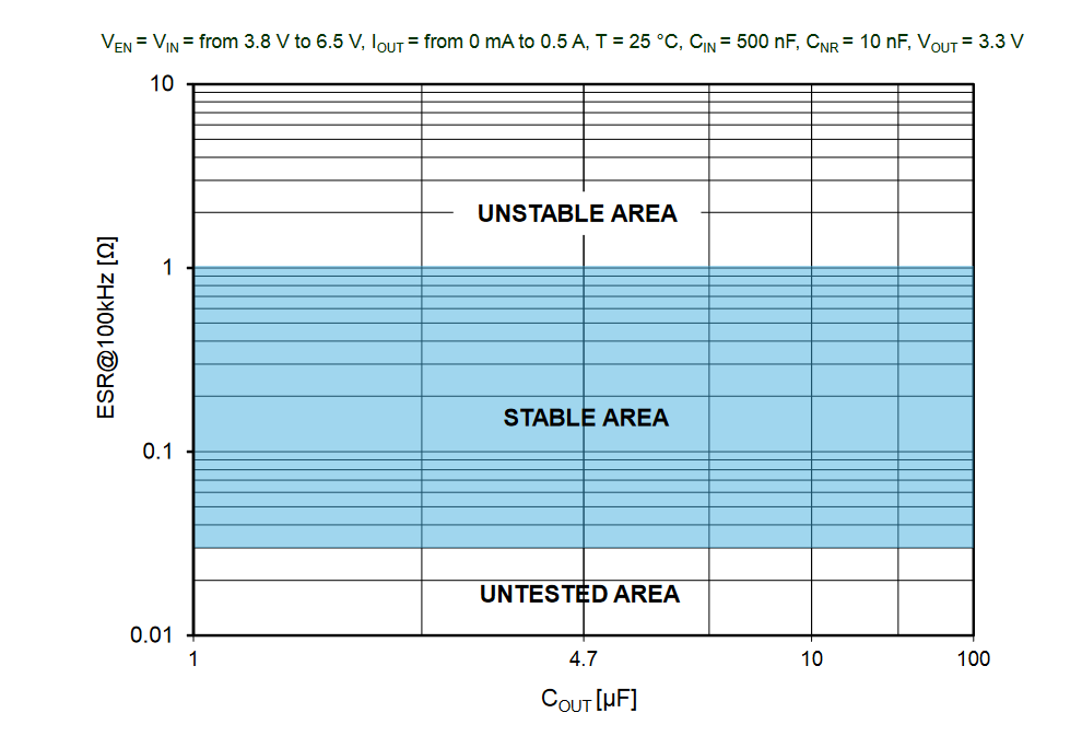
(Image source: LDLN050 datasheet)
Rated Capacitance ≠ Effective Capacitance
Unfortunately, we don’t live in an ideal world; thus we cannot simply choose an output capacitor by the rated capacitance, some manufacturers like Texas Instruments also mention this in their datasheet:
Effective output capacitance that takes bias, temperature, and
aging effects into consideration must be greater than 0.5 μF to ensure stability of the device
Initial tolerance, capacitance change over temperature, DC-bias and aging are factors that negatively impact a MLCCs performance.
Information about these factors is typically not found in the components datasheet, reputable capacitor manufacturers like Würth Elektronik, Kemet, Samsung provide this information on a separate web platform. For this appnote we used the REDEXPERT platform by Würth.
Initial tolerance
The initial tolerance simply specifies how much the capacitance may vary from the specified value, this does not take into account other derating factors. 5%,10% and 20% are typical tolerance values for capacitors, it is typical that the capacitance will be lower rather than higher than the specified value.
Temperature
Class 2 MLCCs experience a change of capacitance over their rated temperature range, how much the capacitance can vary is specified by the EIA-RS-198 coding.
| min. temp. | max. temp | max. capacitance over temp. range |
|---|---|---|
| X = −55 °C | 4 = +65 °C | F = +7,5 |
| Y = −30 °C | 5 = +85 °C | P = ±10% |
| Z = +10 °C | 6 = +105 °C | R = ±15% |
| 7 = +125 °C | S = ±22% | |
| 8 = 150 °C | T = +22/−33% | |
| 9 = +200 °C | U = +22/−56% | |
| V = +22/−82% |
Due to their high capacitance change over temperature, Y5V capacitors are not recommended and are also not offered by many vendors anymore. X5R and X7R have become the standard type in the industry. As linear voltage regulators emit heat, it is recommended to use X7R capacitors due to their higher temperature rating.
Graph: Typical capacitance change over temperature.
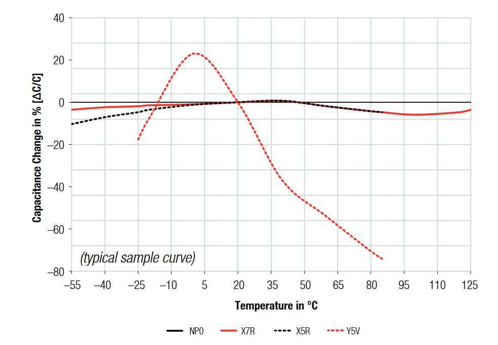
(Image source: Würth Elektronik / we-online.net)
DC Bias
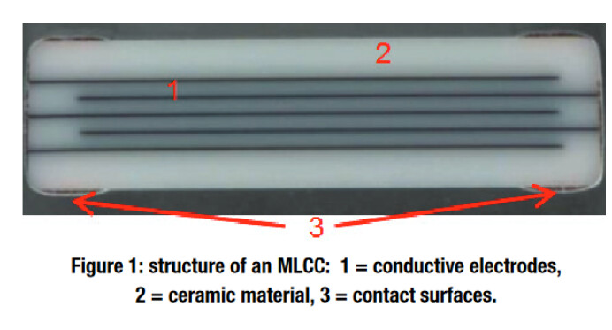
Applying a voltage to a MLCC capacitor causes a drop in capacitance due to the polarization of the dielectric material, which is made up of barium titanate. The strength of this effect is dependent on the size of the capacitor and the applied voltage.
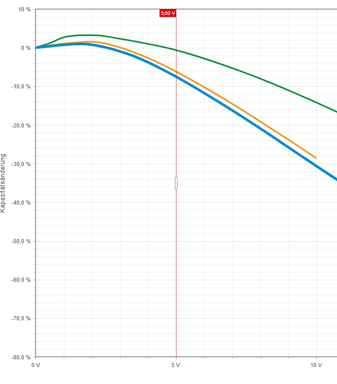
Graph: Change in capacitance through DC Bias. 1µF 6.3V rated MLCCs in various package sizes.
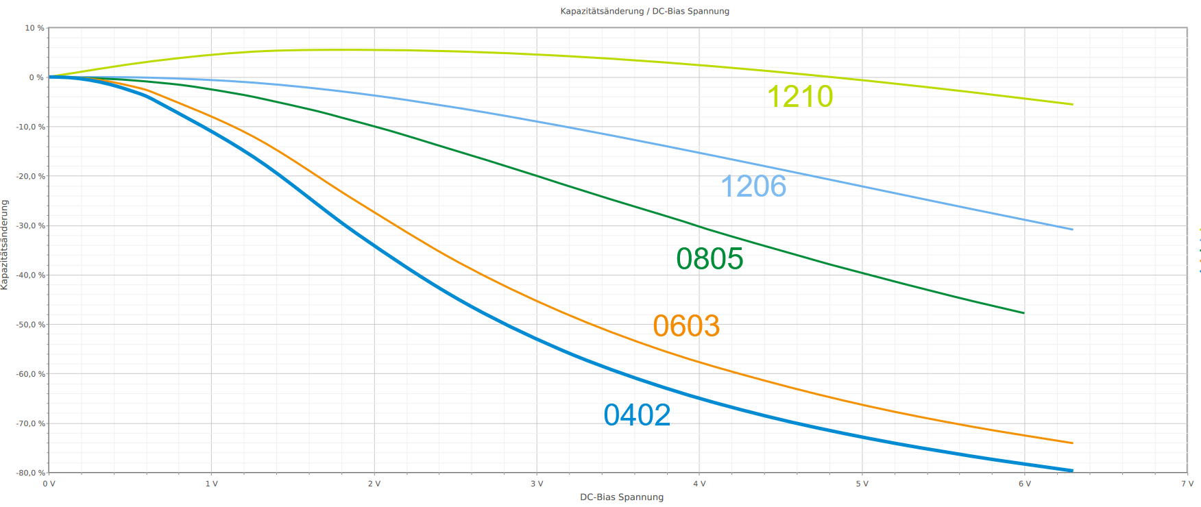
(Image source: Würth Elektronik REDEXPERT)
Smaller capacitors operated close to the maximum rated voltage may lose up to 80% of their rated capacitance, larger sized caps may only lose about 5%.
(Image source: Würth Elektronik / we-online.net)
To make smaller capacitors with the same capacitance, the manufacturer has to add more “layers” to the MLCC structure, resulting in thinner layers, which saturate more easily.
Aging
MLCC capacitors Age and their capacitance reduces around 6% after 1000 h for X5R caps and ~2.5% after 1000 h for X7R.
Design Example
Let’s select an input and output capacitor for the TLV1117LV LDO.
- VIN = 5V
- VOUT = 3.3V
The datasheet reads:
Effective output capacitance that takes bias, temperature, and aging effects into consideration must be greater than 0.5 μF to ensure stability of the device.
To simplify the bill of Material, we’ll use the same capacitor for input and output. We’ll shall use an X7R capacitor with an effective capacitance of 1µF at 5V in an 0805 package rated up to 125 degree Celsius. The TLV1117LV uses a regulation circuitry that does not require a minimum ESR, so it is not covered.
0805 was chosen as package size as a balanced option between the smaller 0402 and 0603 packages which experience a higher DC Bias and the 1206 and 1210 packages which require large amounts of space.
125 degree Celsius was selected as the upper temperature limit as the capacitors will be placed in close proximity to the LDO which emits heat.
A voltage rating of 10V or higher was selected for the initial search, as 6.3V would be too close to the 5V on the input side.
REDEXPERT from Würth was used to look up a suitable capacitor, which allows for quick filtering of capacitors by parameters.
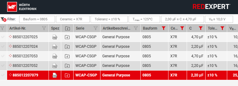
Comparing the DC Bias of 2.2µF capacitors rated at 10V, 16V and 25V showed that there was no significant difference.
Considering all derating factors, the 2.2µF 10V version provides a comfortable margin, providing a effective capacitance of 1.5µF in the worst case.

A capacitor with an even higher capacity or voltage rating may be chosen, but this would result in higher component cost, so this configuration is the most balanced.
IMPORTANT NOTICE
AISLER assumes no liability for design assistance provided by this appnote. Engineers/designers are responsible for their design.